|
Setting the stage:
Our original solar
panels were mounted on or near our house but it soon became apparent
that the maple trees south of the house were blocking the sun –
especially in the winter when we needed power the most. What we were
after was a spot to relocate the panels that had dawn-to-dusk direct sun
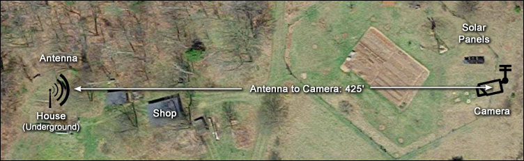
all year round. The closest spot is over 400’ east of the house, near
our water pumping windmill.
Normally it would not be economical
to try to transmit low voltage DC that distance without significant
voltage drop; the cables would need to be large and expensive.
Fortunately we managed to obtain, as salvage ($50), about a quarter mile
of 100-pair phone line. This cable is about 1-1/2’ in diameter including
its significant shielding and insulation and we had a couple of segments
that were well over 400’ long. I stripped each of the 200 ~19 ga. wires
a couple of inches, stuffed them into a short section of copper tube,
hammered the tube flat and flowed solder into the joint – on each end of
two cables – 800 wires to strip, all together. I then drilled a 3/8”
hole in each connector and celebrated!
We ran these cables on top
of the ground from the new array location to a spot just outside the
house. Over several years we buried the cables to protect them from us
and our inclination to try to mow too close to them. Over the years, (we
installed our first 32 Watt Arco panel in 1981) the array has grown to a
bit over 1000 watts and runs at 24 volts DC. Voltage drop is minimal and
actually somewhat protects our older 50 Amp MPPT charge controller.
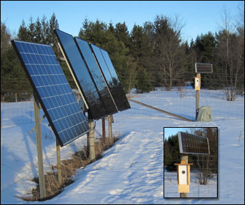
Solar array and camera box
Enter the PanelCam:
Every morning in winter we would look out towards the array
and try to guess if there was enough snow on the panels to warrant
getting dressed for the cold and trekking out clean off the panels. We
can see the array from the house but since it is directly east of the
house we can only see the edge of the solar panels. We have long
considered, half joking, installing a remote camera, aimed at the front
of the array but dismissed the idea because of cost and in truth, we
didn’t mind those early morning walks all that much.
Before I go
any further I should come clean on another point. I have not had a lot
of glowing success with electronic projects in the past, having smoked
several circuits including a homemade solar panel tracker. But I had
been reading about Arduinos. Those small microcontrollers were designed in
Italy to help young folks learn about electronics and programming. Since
I wouldn’t have to invent my circuits from scratch I figured that I
might have a chance with those little guys.
The PanelCam project
is made up of two separate systems; 1) inexpensive Wi-Fi ‘security’
camera and 2) a circuit that would switch the camera on when needed and
off when not – which is most of the time. The reasons for this are that
because of its remote location the camera needs to be battery powered
and more importantly, if the camera was on and connected to the Internet
all the time it would blow our limited Internet plan into overtime, many
times over.
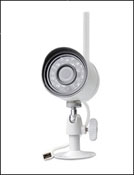
FunLux Wi-Fi Camera
I found a reasonably priced ($35) ‘FunLux’ Wi-Fi
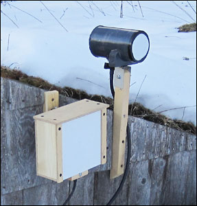
camera that has an external antenna and can run on 5 volts DC. I have
mounted the camera in a mostly weatherproof enclosure on a fence post
out in the garden. To increase the range of the camera I also installed
a small, 6” square, parabolic reflector with the antenna right at the
focal point of the reflector.
The Cantenna:
Two
antennas on house roof - 'Cantenna' on right
At the house end, because our router is inside, below the
earth-covered roof, I installed a TP-Link Wi-Fi Extender that also has a
single external antenna. This unit is connected via 6’ of expensive
low-loss cable to a homemade, very directional ‘Cantenna’ that aims
right at the camera enclosure – line of sight with no obstructions.
Other than constructing the cantenna, phase one of the project went
pretty quickly. Here’s a brief rundown on the cantenna construction
which is totally borrowed from a couple of web sites.
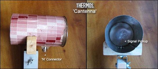
Cantenna constructed from old Thermos shell
My research
showed that to build this antenna I would need a can about 3-5/8” in
diameter and 7” tall but I was unable to find a can that size in the
grocery store. I did have the shell of an old thermos bottle that I
ended up using. Here are a couple of photos of the first try with the
thermos. I subsequently refined the thing by soldering on a new, flat, shiny
bottom and moved the placement of the receiver wire a little. A little
paint and a cover to keep out the snow and it was ready to go.
The Switch Circuit:
Arduinos
(pronounced like: are-‘Dween-ohs) are cool! They’re small
microcontrollers capable of handling multiple inputs and outputs, draw
very little current and with the addition of battery are totally
independent little units. They are programmable, meaning with a few
instructions you can have it do your bidding. I began with a common Arduino
Uno, about $24 for the original Made in Italy version. The neat thing is
that the source code for the microcontroller boards and everything else
about them is officially ‘Open Source’. Because of space constraints I
chose to use a couple of smaller Arduino Nano clones that cost around $4
each.
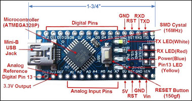
Arduino Nano layout - (note size)
Arduinos are
programmed using versions of the ‘C’ and ‘C++’ languages and a free,
downloadable programming environment (IDE).. Although I have been
programming computers starting back in
1975 on an IBM 5100 mini computer and subsequently using a few other
programming languages, I had never done anything with ‘C’ before.
(As an
aside, that IBM 5100 cost my employer about $16,000 with 16 MB of
memory. We upgraded it to its maximum of 64 MB (yes, that’s megabytes!)
at $1,250 per each of three memory boards. That’s in 1975 dollars.)
Basically what I did was hook up a Wi-Fi transceiver to each of the
Arduinos and then configured the circuits so one, the one at the house,
is the transmitter, and the other, the one out with the camera, as a
receiver.
The Transmitter:
The
unit in the house is set up with a simple push button, and a bit of
code, to send either an ON or OFF message to the receiver. This unit’s
Wi-Fi radio is connected to a 6’ low-loss cable
designed to be used with 2.4 GHz devices. On the far end of that cable
is the transmitter’s original little ‘rubber duckie’ type antenna with
its own parabolic reflector. This is mounted inside a small weatherproof
box and aimed at the camera box out in the garden. The transmitter and
the Wi-Fi Extender are each powered by their own DC-DC buck converter.
The transmitter runs on 7 volts DC and the extender on 9 volts DC. The
transmitter also has a small 4-line LCD display that confirms that the
signal was sent & received OK and as a bonus, shows the temperature out
at the camera box.
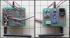
Receiver circuit board
The Receiver:
This unit is mounted in the lower part of the camera box with its
own directional parabolic reflector aimed back at the house. When the
receiver gets a valid ON or OFF message it confirms this by sending a
quick little ‘ack’ message back to the transmitter. And cool enough, I
programmed it to tack the temperature onto that message. When it
receives an ON message the Arduino activates a small relay that sends
power to the camera and simultaneously lights up a pretty bright LED
that we can see from the house to confirm that all’s well and the camera
is indeed ON. An OFF message does the opposite and the OFF state is
confirmed by the LED being OFF.
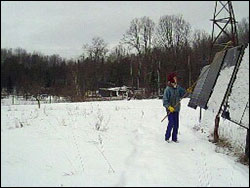
View from the PanelCam
Operation:
If there is any chance that the panels might have snow on
them I flip a switch at my desk that turns on the power to the Extender
and transmitter. I then go over to the ON/OFF button and press it a
couple of times so the camera cycles on and off and then ends up ON
according to the display. I probably should refine this a bit in the
code but for now the temperature only shows correctly if the receiver is
cycled on & off & on again. I’d rather it didn’t need to do that but I
can live with it for now.
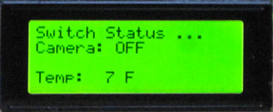
LCD Display shows camera
status and temperature at camera
I wait a minute or so for the extender
to boot up and for our router to find it. Then I fire up the FunLux app
on my Kindle Fire HDX 8.9 tablet and if all went well I can see a nice
HD snapshot of the array. Another click and a live HD video of what’s
going on out in the orchard displays. This works well much of the time
but sometimes the FunLux app shows “Device Off Line”. I then usually
force-close the app and try again and usually the system works as
planned. In the app you can turn the infrared night lighting on or off
and the images in night darkness are surprisingly clear though of
course, colorless.
Summary:
What might I do differently?
1) I might just buy
a little TP-Link 9 Db external antenna, about $21, to use in place of
the cantenna. It was an interesting sub-project but it took me nearly a
month to build and fine-tune it.
2) I might shop around for a
different camera. The camera seems to be working fine but the FunLux app
is a bit clunky and at times totally unresponsive. Unfortunately, I
think I’m stuck with that app but if you know otherwise, let me know,
OK?
Cost breakdown for the whole system:
• Camera, FunLux 720p
HD … $35
• TP-Link WiFi Extender … $20
• Arduinos Nano Clones (2)
… $8
• nRF24L01 (+) wireless Transceivers (2) … $11
• 6’ Low-Loss
antenna cables ~ $25 ea. … $50
• 4-Line LCD Display (Frentaly) … $13
• 2-Chanel relay (SunFounder) … $7
• DC- DC converters (4) ~$10 ea …
$40
• Waterproof DS18b20 Temperature sensor … $3
• Misc. perf
board, wire & solder … ~ $15
Total (Unless I’ve forgotten something)
… $ 202
|
|
Code for the Transmitter:
// PanelCam Switcher TX using AckPayload - the
master or the transmitter //
// By Steve Schmeck 1/27/2017 //
#include <LiquidCrystal_I2C.h>
#include <SPI.h>
#include
<nRF24L01.h>
#include <RF24.h>
#include <Button.h>
#define CE_PIN 9 // Define radio pins
#define CSN_PIN 10 //
LiquidCrystal_I2C lcd(0x3F,20,4); // set the LCD address to 0x3F
for a 20 chars and 4 line display
const byte slaveAddress[5]
= {'R','x','A','A','A'}; // Set 'slave' or remote address
RF24 radio(CE_PIN, CSN_PIN); // Create an instance of 'radio'
char dataToSend[2]; // Data to be sent to remote unit
int
ackData[2]; // Holds the value coming from the remote unit
bool
newData = false;
char onOffMsg[12]{"Camera: OFF"}; // ON or
OFF message to be sent initially to display
int temperature;
int sendTemp = 1; // Ask for temp from slave? 1 = yes, 0 = no
int
justPressedButton = 0; // Indicator of just-pressed button; 1 or 2
int lastSentButton = 2; // Indicator of most recently pressed
button; 1 or 2 = ON or OFF
Button buttonOn2 =
Button(2,PULLUP); // ON/OFF button on pin 2; PULLUP so pin 2 does
not 'float'
//===============
void setup() {
Serial.begin(9600);
Serial.println("PanelCam TX starting ...");
lcd.init(); // initialize the lcd
lcd.backlight(); // turn
on backlight
initializeDisplay(); // Display the opening
screen (function)
radio.begin(); // Turn radio on
radio.setChannel(108); // Above most Wifi Channels
radio.setDataRate( RF24_250KBPS );
// Set the PA Level to
prevent power supply related issues and/or overpowering units
//
in close proximity. RF24_PA_MAX is default.
// radio.setPALevel(RF24_PA_MIN);
// Uncomment for minimum power
// radio.setPALevel(RF24_PA_LOW);
// Uncomment for low power
radio.setPALevel(RF24_PA_HIGH); //
Uncomment for high power
// radio.setPALevel(RF24_PA_MAX); //
Uncomment for maximum power
radio.enableAckPayload();
radio.setRetries(3,5); // delay, count
radio.openWritingPipe(slaveAddress);
// Initialize temperature on display //
send();
temperature = ackData[0];
showData();
} // End of setup
//=============
void loop() {
getButtonPress(); // get
button press
} // End of void loop //
//================
void send() {
bool rslt;
rslt =
radio.write( &dataToSend, sizeof(dataToSend) );
// Using sizeof()
as it gives the size as the number of bytes.
if (rslt) {
if (
radio.isAckPayloadAvailable() ) {
radio.read(&ackData, sizeof(ackData));
newData = true;
}
else {
Serial.println(" Acknowledge but
no data ");
}
}
else {
Serial.println(" Tx failed");
}
} // End of send function
//=================
void
getButtonPress(){
// Get button press data and assign it to 'dataToSend'
variable
// test for button press on pin 2 (ON/OFF button) //
if(buttonOn2.isPressed()){
Serial.print("lastSentButton = ");
Serial.println(lastSentButton);
if(lastSentButton == 2){ //
If OFF sent last then ...
strcpy (dataToSend, "1"); // Switch as
though ON button has been pressed
strcpy (onOffMsg, "Camera: ON
");
send();
showData();
Serial.print("dataToSend = ");
Serial.println(dataToSend);
Serial.print("onOffMsg = ");
Serial.println(onOffMsg);
}
if(lastSentButton == 1){ // If ON
sent last then ...
strcpy (dataToSend, "2"); // Switch as though
OFF button has been pressed
strcpy (onOffMsg, "Camera: OFF");
send();
showData();
Serial.print("dataToSend = ");
Serial.println(dataToSend);
Serial.print("onOffMsg = ");
Serial.println(onOffMsg);
}
if(onOffMsg[9] == 'N'){
lastSentButton = 1;
}
if(onOffMsg[9] == 'F'){
lastSentButton = 2;
}
Serial.print("New LastSentButton = ");
Serial.println(lastSentButton);
Serial.println("------------------------");
}
delay(200);
} // end of getButtonPress function
//=================
void showData() {
if (newData == true) {
temperature = ackData[0];
updateDisplay(); // Display temperature
on LED display
newData = false;
}
} // End of showData
function
//=================
void updateDisplay(){ //
Updates the data shown on the LCD display
lcd.setCursor(0,0);
// Line 1 - Header
lcd.print("Switch Status ...");
lcd.setCursor(0,1); // Line 2 - switch state
lcd.print(onOffMsg);
lcd.setCursor(0,3); // Line 4 - Temperature
lcd.print("Temp:
");
lcd.print(temperature);
lcd.print(" F");
} // End
of updateDisplay function
//=================
void
initializeDisplay(){ // Initializes the LED display with openinf
screen at startup
lcd.setCursor(0,0); // Line 1 - Header
lcd.print("PanelCam Switcher");
// Line 2 - Blank - for future
use
// Line 3 - Blank - for future use
// Line 4 - Blank - for
future use
delay(1000);
} // End of initializeDisplay function
//====== END ==========
|
|
Code for the Receiver:
// PanelCam Switcher RX using AckPayload - the slave
or the receiver //
// By Steve Schmeck 1-22-2017 //
#include <SPI.h> // radio interface
#include <nRF24L01.h> // for
radio
#include <RF24.h> // for radio
#include <OneWire.h> //
for temp sensor
#include <DallasTemperature.h> // for temp sensor
#include "LowPower.h" // power-saving
#define CE_PIN 9
#define CSN_PIN 10
const byte thisSlaveAddress[5] = {'R','x','A','A','A'};
RF24 radio(CE_PIN, CSN_PIN); // Create an instance of 'radio'
char dataReceived[10]; // this must match dataToSend in the TX
int ackData[2] = {109, -4000}; // the two values to be sent to the
master (placeholder numbers)
bool newData = false;
#define
ONE_WIRE_BUS 3 // sensor data line connected to Pin 3
OneWire
ourWire(ONE_WIRE_BUS); // Set up a oneWire instance to communicate
with any OneWire device
DallasTemperature sensors(&ourWire); //
Tell Dallas Temperature Library to use oneWire Library
int
remTemp; // int variable for sending temperature (remote
temperature)
//==============
void setup() {
Serial.begin(9600);
Serial.println("PanelCam RxAckPayload
Starting");
radio.begin(); // Turn radio on
radio.setChannel(108);
// Above most Wifi Channels
radio.setDataRate( RF24_250KBPS ); //
RF24_250KBPS for 250kbs, RF24_1MBPS for 1Mbps, or RF24_2MBPS for
2Mbps
// Set slow to assure reliability
// Set the PA
Level to prevent power supply related issues and/or overpowering
units
// in close proximity. RF24_PA_MAX is default.
//
radio.setPALevel(RF24_PA_MIN); // Uncomment for minimum power
//
radio.setPALevel(RF24_PA_LOW); // Uncomment for low power
radio.setPALevel(RF24_PA_HIGH); // Uncomment for high power
//
radio.setPALevel(RF24_PA_MAX); // Uncomment for maximum power
radio.openReadingPipe(1, thisSlaveAddress);
radio.enableAckPayload();
getTempFromSensor(); // get initial
temp from sensor & assign it to ackData
radio.writeAckPayload(1,
&ackData, sizeof(ackData)); // pre-load temperature data
radio.startListening(); // Power Note: this uses ~ 50 mA
pinMode(2,OUTPUT); // set pin 2 to activate relay
digitalWrite(2,LOW);
// set pin 2 LOW (camera is OFF)
}
// END of setup
//==========
void loop() {
getTempFromSensor();
LowPower.idle(SLEEP_2S, ADC_OFF, TIMER2_OFF, TIMER1_OFF, TIMER0_OFF,
SPI_OFF, USART0_OFF, TWI_OFF);
// Enter power down state for
4 seconds with ADC and BOD module disabled - not currently enabled
// LowPower.powerDown(SLEEP_4S, ADC_OFF, BOD_OFF);
getData();
showData();
Serial.println(dataReceived);
// DO
something with the data
if(dataReceived[0] == '1'){
Serial.println("got to dataReseived");
digitalWrite(2,HIGH); //
set pin 2 HIGH (camera is ON)
}
if(dataReceived[0] ==
'2'){
digitalWrite(2,LOW); // set pin 2 LOW (camera is OFF)
}
// END of Do Something
}
// END of void
//============
void getData() {
if ( radio.available() ) {
radio.read( &dataReceived, sizeof(dataReceived) );
//
updateReplyData();
newData = true;
}
}
// END of getData
//================
void showData() {
if (newData == true)
{
Serial.print("Data received ");
Serial.println(dataReceived);
Serial.print(" ackPayload sent ");
Serial.print(ackData[0]);
Serial.print(", ");
Serial.println(ackData[1]);
newData =
false;
}
}
// END of showData
//================
void getTempFromSensor() {
// Get temperature from sensor
sensors.begin(); // Start up the DallasTemperature library
sensors.requestTemperatures(); // Send the command to get
temperatures
remTemp = sensors.getTempFByIndex(0);
ackData[0]
=remTemp;
radio.writeAckPayload(1, &ackData, sizeof(ackData));
// load the payload for the next time
} // END of
getTempFromSensor
|